Arduino Home Automation Using RF
Home automation is one of in demand concepts in today’s world. Hobbyists do simple automation systems with the components readily available. If we are more concerned about the reliability and performance of the system, then we can go for the expensive Home Automation Consoles.
Home automation reduces the physical efforts and integrates the control for any number of appliances in to a single control unit. Hence, a simple home automation system is a remote control of different electrical appliances i.e. turning them on or off with the help of a remote.
There are many ways to implement this remote control system. With the extensive use of smart phones and tablets, Bluetooth may be the best option to implement the home automation. And one is implemented here in Bluetooth based Home Automation using Arduino. The other methods of remote controlled home automation system are ZigBee, Wi-Fi, Radio Frequency (RF Module), GSM etc.
In this project, a simple but efficient home automation system using RF Module (Transmitter – Receiver pair) is designed. The system is designed with Arduino (ATmega 328) as the main processing unit.
Circuit Diagram
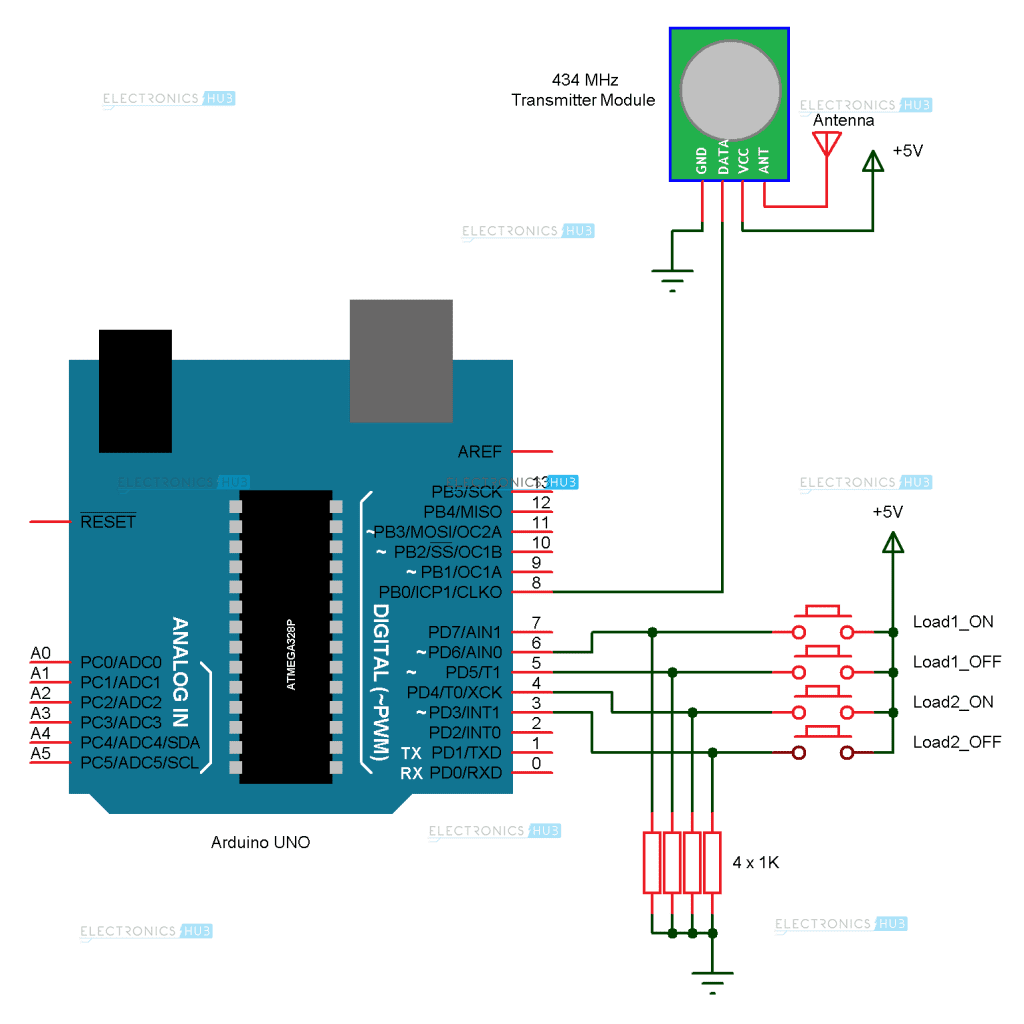
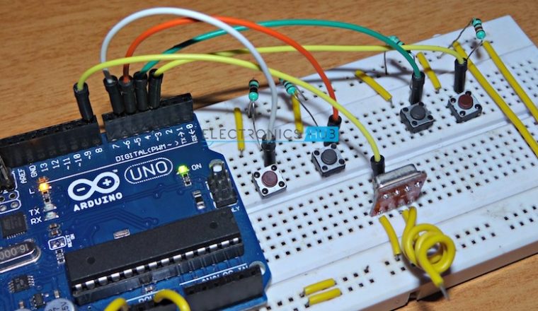
The circuit diagram is divided in to the transmitter section and receiver section for easy understanding. The transmitter section of the project is shown on the following image.
The receiver section of the project is shown in the following image.
Required Component
The list of components mentioned here are specifically for controlling two different loads. The list of components may vary if the no. of loads is more.
Transmitter Section
- Arduino UNO
- 434 MHz RF Transmitter
- Push Buttons X 4
- 1 KΩ Resistor X 4
- Prototyping Board
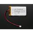
- 9V Battery
- Connecting wires
Receiver Section
- Arduino UNO
- 434 MHz RF Receiver
- 2N2222 NPN Transistor X 2
- 1 KΩ Resistor X 2
- 1N4007 PN Junction Diode X 2
- 12V Relay X 2
- Prototyping Board
- Power Supply (Adapter)
- Connecting wires
Component Description
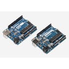
Arduino UNO:
Two Arduino UNO’s is used in the project, one in the transmitter section which reads the inputs from switches and transmit the message and the other is used in receiver section to decode the message and control the loads.
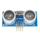
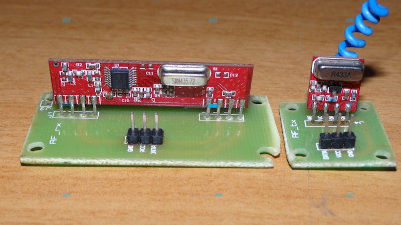
434 MHz RF Module:
The 434 MHz Radio Frequency Transmitter – Receiver Module is the best and cheapest way to implement a wireless communication for a reasonably longer ranges.
Relay Board:
A relay board consists of all the components that are required for a relay to be operated by a microcontroller. A four channel relay board is used although only two relays are used in the practical implementation.
Circuit Design
The design of the circuit is explained with respect to transmitter section and receiver section individually.
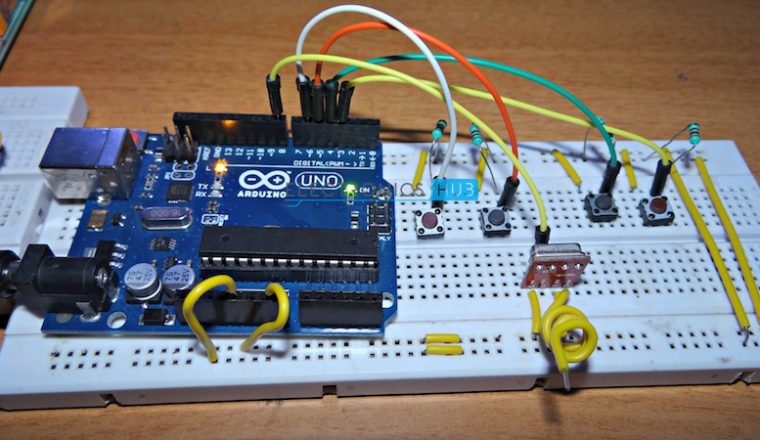
Transmitter Circuit Design:
The first component we need to connect to the Arduino UNO is the RF Transmitter module. The data in pin of the RF Transmitter module is connected to the 8th digital I/O pin of Arduino. The other pins of the transmitter module i.e. VCC and GND are connected to 5V and ground pins of the Arduino respectively. An optional antenna wire can be connected to the antenna pin of the transmitter module.
The next step is to connect the push buttons. First, we need to pull down the digital I/O pins 3 through 6 with the help of four 1KΩ resistors. Then connect four switches to these four pins with the other ends of the switches connected to 5V supply.
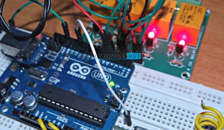
Receiver Circuit Design:
The RF Receiver receives the data through RF links and must transmit this data to the Arduino. Hence, the data out pin of the receiver module must be connected to digital I/O pin 11 of the Arduino.
The VCC and GND pins of the receiver module are connected to 3.3V and ground pins of the Arduino. An antenna can be connected to the antenna terminal of the module.
If you are using a relay board, as we are in this project, simply connect the digital I/O pins 4 and 5 of the Arduino to the input pins of the relay.
If you are not using the relay board, the connections must be made as per the circuit diagram.
Note: We need to be extremely careful when connecting AC Mains supply to the relay board.
Project Working Process
Home Automation System is a useful and helpful way to manage electrical appliances without any physical contact with the switch. This is possible by utilizing the wireless communication technologies. In this project, an RF based home automation system is implemented using Arduino. The working of the project is explained here.
At the transmitter section, the Arduino continuously monitors the status of the switches (or buttons). Whenever a switch is pressed, a logic HIGH is detected at that particular I/O pin. As a result, the Arduino transmits a suitable message corresponding to the switch pressed.
For example, if LOAD1_ON switch, which is connected to pin 6, is pressed, Arduino detects a logic HIGH at pin 6. Hence, Arduino sends a message as “@ABC$” via the RF transmitter.
At the receiver end, the RF receiver receives this message and transmits the same to Arduino for decoding. When the Arduino at the receiver end decodes the message and understands that the transmitter characters are “@ABC$”, it then writes a HIGH signal on the digital I/O pin 4.
As a result, the relay connected to load 1 is activated and the load is turned on.
Similar actions are performed when other switches are pushed.
If there is any error in the data transmission i.e. the desired data is not transmitted, the Arduino at the receiver section lights up the error LED which is connected to the 13th pin.
A data transmission successful LED and an error buzzer can also be implemented to indicate those actions more efficiently.
Applications
- Although Bluetooth based home automations are easy to implement as almost everyone has a smart phone, the advantage of the RF based home automation system is the range of communication. RF based system is useful if we have a large house where Bluetooth might go out of range.
- The system can be expanded to a smart home system with security by integrating several sensors like temperature, humidity, light and security devices like burglar sensors, CCTV’s etc.
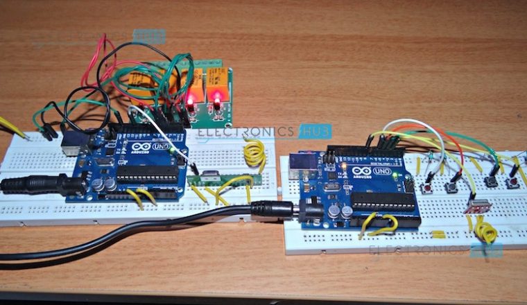
Project Images
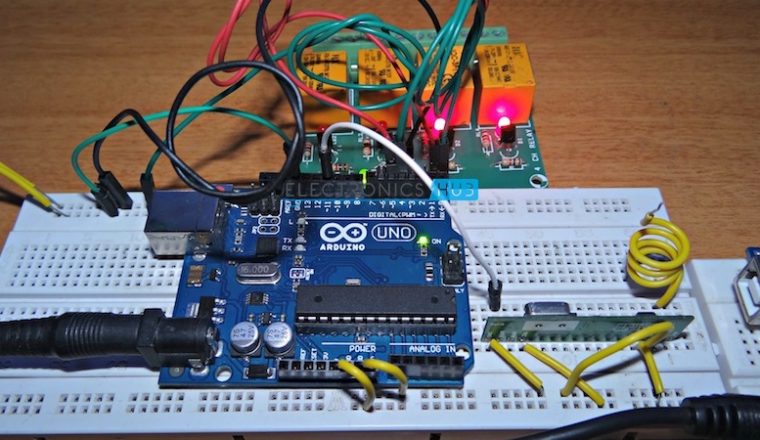 Arduino Home Automation using RF
Code
For Transmitter Part
| #include <VirtualWire.h> |
| const int RF_TX_PIN = 8; |
| const int load1_ON = 6; |
| const int load1_OFF = 5; |
| const int load2_ON = 4; |
| const int load2_OFF = 3; |
| |
| char msg[6] = ""; |
| int load1ON = 0; |
| int load1OFF = 0; |
| int load2ON = 0; |
| int load2OFF = 0; |
| |
| void setup() |
| { |
| vw_set_ptt_inverted(true); |
| vw_set_tx_pin(RF_TX_PIN); |
| vw_setup(2000); |
| |
| pinMode(load1_ON, INPUT); |
| pinMode(load1_OFF, INPUT); |
| pinMode(load2_ON, INPUT); |
| pinMode(load2_OFF, INPUT); |
| } |
| |
| void loop() |
| { |
| load1ON = digitalRead(load1_ON); |
| load1OFF = digitalRead(load1_OFF); |
| load2ON = digitalRead(load2_ON); |
| load2OFF = digitalRead(load2_OFF); |
| |
| if (load1ON == HIGH) |
| { |
| strcpy(msg, "@ABC$"); |
| } |
| |
| if (load1OFF == HIGH) |
| { |
| strcpy(msg, "@BOFF$"); |
| } |
| |
| if (load2ON == HIGH) |
| { |
| strcpy(msg, "@FON$"); |
| } |
| |
| if (load2OFF == HIGH) |
| { |
| strcpy(msg, "@FOFF$"); |
| } |
| |
| if(strlen(msg)>0) |
| { |
| sendMsg(msg); |
| } |
| |
| strcpy(msg, ""); |
| resetLoads(); |
| } |
| |
| void sendMsg(char msg[]) |
| { |
| vw_send((uint8_t *)msg, strlen(msg)); |
| vw_wait_tx(); |
| delay(400); |
| } |
| |
| |
| void resetLoads() |
| { |
| load1ON = 0; |
| load1OFF = 0; |
| load2ON = 0; |
| load2OFF = 0; |
| } |
For Receiver Part
| #include <VirtualWire.h> |
| const int RF_RX_PIN = 11; |
| const int load1 = 4; |
| const int load2 = 5; |
| const int errorLED = 13; |
| |
| boolean bload1 = false; |
| boolean bload2 = false; |
| |
| void setup() |
| { |
| vw_set_ptt_inverted(true); |
| vw_set_rx_pin(RF_RX_PIN); |
| vw_setup(2000); |
| vw_rx_start(); |
| |
| pinMode(errorLED, OUTPUT); |
| pinMode(load1, OUTPUT); |
| pinMode(load2, OUTPUT); |
| bload1 = false; |
| bload2 = false; |
| } |
| |
| void loop() |
| { |
| uint8_t buf[VW_MAX_MESSAGE_LEN]; |
| uint8_t buflen = VW_MAX_MESSAGE_LEN; |
| if(vw_get_message(buf, &buflen)) |
| { |
| delay(500); |
| messageDecode ( (char *) buf); |
| delay(500); |
| } |
| |
| if(bload1 == true) |
| { |
| digitalWrite(load1, HIGH); |
| } |
| |
| if(bload1 == false) |
| { |
| digitalWrite(load1, LOW); |
| } |
| |
| if(bload2 == true) |
| { |
| digitalWrite(load2, HIGH); |
| } |
| |
| if(bload2 == false) |
| { |
| digitalWrite(load2, LOW); |
| } |
| } |
| |
| void messageDecode(char msg[]) |
| { |
| if (strlen(msg) ==0) |
| { |
| ErrorLED(); |
| return; |
| } |
| |
| |
| if ( compareMessage(msg, '@') == false || compareMessage(msg, '$') == false) |
| { |
| ErrorLED(); |
| return; |
| } |
| |
| |
| char cTag[5] =""; |
| int index =0; |
| int iLoop = IndexOf(msg,'@'); |
| |
| if(iLoop == -1) |
| { |
| ErrorLED(); |
| return; |
| } |
| |
| iLoop++; |
| |
| while (iLoop < strlen(msg)) |
| { |
| if(msg[iLoop] == '$') |
| { |
| break; |
| } |
| else |
| { |
| cTag[index] = msg[iLoop]; |
| index++; |
| } |
| |
| iLoop ++; |
| } |
| |
| String sTag = String(cTag); |
| |
| if (sTag.equals("ABC")) |
| { |
| bload1 = true; |
| } |
| |
| if (sTag.equals("BOFF")) |
| { |
| bload1 = false; |
| } |
| |
| if (sTag.equals("FON")) |
| { |
| bload2 = true; |
| } |
| |
| if (sTag.equals("FOFF")) |
| { |
| bload2 = false; |
| } |
| |
| } |
| |
| int IndexOf(char msg[], char tag) |
| { |
| if (strlen(msg) ==0) return false; |
| boolean bFlag = false; |
| int iIndex = -1; |
| |
| for( int i=0; i<strlen(msg); i++) |
| { |
| if(msg[i]== tag) |
| iIndex = i; |
| } |
| |
| return iIndex; |
| } |
| |
| boolean compareMessage (char msg[], char tag) |
| { |
| if (strlen(msg) ==0) return false; |
| boolean bFlag = false; |
| |
| for( int i=0; i<strlen(msg); i++) |
| { |
| if(msg[i]== tag) |
| bFlag = true; |
| } |
| |
| return bFlag; |
| } |
| |
| void ErrorLED() |
| { |
| digitalWrite(errorLED, HIGH); |
| delay(500); |
| digitalWrite(errorLED, LOW); |
| } |


 by
by